Astrophotonics
JRA6 Workpackage of OPTICON
Optical Infrared Coordination Network for Astronomy, Horizon 2020
1. Introduction and work package aim
The objective of the work-package is to develop revolutionary guided-wave photonic technologies that can efficiently couple seeing-limited and partially adaptive optics corrected telescope images into highly stable and precise optical/infrared spectrographs, with very little optical loss or degradation of the signal thereby enhancing the sensitivity and functionality of the next generation of ground-based optical/infrared instrumentation for European and Worldwide astronomical facilities, including the Extremely Large Telescope (ELT).
2. Research Methodology
The astrophotonics work-package is pursuing complementary developments via technologies that increase the sensitivity and stability of precision spectrographs, along with technologies that enhance the efficiency and functionality of light coupling from adaptive optics and natural seeing limited telescope faculties. These technologies include: multicore fibre photonic lanterns that provide ultra-low loss connections between multimode and single- mode waveguides; 3D waveguide structures that can arbitrarily reformat the light pattern by routing the single-mode waveguides and when combined with photonic lanterns can facilitate the implementation of efficient small diffraction- limited spectrographs when the input is far from diffraction limited; wavefront tilt sensing, using 3D printed microlens coupling or multicore fibre-based devices, for wavefront sensing and enhancing the coupling efficiency into guided-wave photonics. Individually or in combination, the technologies can efficiently enable diffraction-limited (or near diffraction limited) instrument functionality benefiting science cases requiring high precision and high throughput visible/NIR spectroscopy on ground-based telescopes.
3. Key results
WP6.1 System Engineering
WP6.1 System Engineering
The team has been developing the top-level requirement specifications based on “use case scenarios” for European instrumentation projects, e.g. ELT-MOS, ELT-HIRES. These are detail in the work package delivery D1 “Initial requirements specification document” and one of the key parameters driving the device design is the number of modes the device is required to support for efficient operation and the dependence on the sampling of the seeing, the telescope diameter and central wavelength are shown in Figure 1.
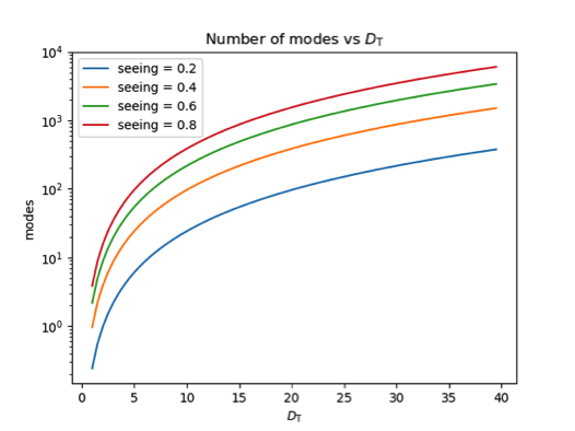
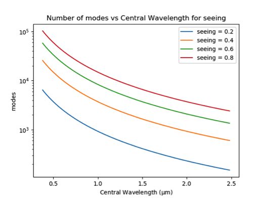
Figure 1 : Left: Number of waveguide modes vs telescope primary mirror diameter, for different on sky waveguide angular apertures (circular) and a wavelength of λ = 1550 nm. Right : Number of waveguide modes vs wavelength of light for different on sky waveguide angular apertures (circular) and a telescope primary mirror diameter of 40 m.
WP6.2 Multicore optical fibre and optical photonics lantern development
Multicore fibre photonic lanterns enable ultra-low loss connections between multimode and single-mode waveguides enabling the implementation of numerous photonic functions (e.g. modal noise suppression), as well as enable the instrument system design to be insensitive to the telescope's focal plane parameters. Thereby the size, mass, cost and instability of spectrographs can be massively reduced for non-diffraction-limited applications.
The main target of the development activities has been characterisation of a near-infrared scrambling fibre fabricated as part of the FP7 OPTICON Astrophotonics development program and the modelling, with associated experimental verification, of multicore photonic lanterns in order to better understand the light propagation within such devices in order to improve the design and optimise the fuction of future devices.
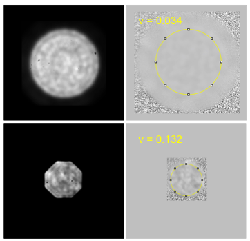
Figure 2 : Fabrication and modal noise scrambling results for a near-infrared optimised multi-core fibre with 73 cores produced by a stack and draw method. Far left : individual capillaries and rods are stacked (top), then packed into an outer tube and drawn to fibre (bottom). Left : Stack design for the 73 core multi-core fibre, the coloured circles are solid silica rod packers of different sizes to keep the structure in place, and grey circles are silica germanium-doped core rods. Centre left : illustration of the optical fibre fabrication process and relevant parts of the fibre drawing. Centre right: Cross section of the fabricated 73 core multi-core fibre. Right: Near-field speckle images of the output of the 73-core fibre (top) and a “state of the art” 50 μm core octagonal fibre comparison (bottom). Far right : Residual speckle image (top) for 73-core fibre and residual speckle image for the octagonal core fibre (bottom)
The 73 core multi-core fibre was designed to suppress the modal noise problems associated with fibre coupled near- infrared precision spectroscopy facilities. The device is a multi-core fibre based photonic lantern (85 μm core, NA 0.11 - corresponding to an ~f/5 beam) structure specifically designed to provide highly efficient phase scrambling in the NIR (central wavelength of 1.64 μm) with a low mode count. The preliminary results demonstrate the device has lower visibility contrast in the residual speckle patterns and higher signal to noise ratio than an octagonal fibre with a similar number of modes at a wavelength of 1.64 μm, i.e. the multi-core photonic lantern device performs better in terms of modal noise reduction than a “current state of the art” octagonal multimode silica fibre. The initial results are very promising and future work is planned to further optimize the phase scrambling ability of such multi-core photonic lanterns and further enhance modal noise suppression characteristics to improve the stability and sensitivity of fibre feed near-infrared precision spectroscopic facilities.
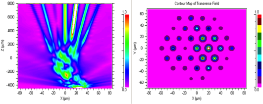
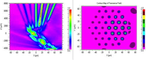
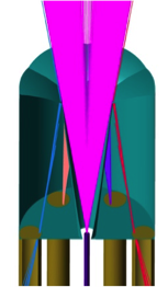
Figure 3 : Left : a cross-section of light propagation through a 37-core photonic lantern with 20 μm bend in the “lower” multi-mode section. Centre left : the corresponding distribution of light intensity at the output of the single-mode section. Centre right : a cross- section of light propagation through a 37 core photonic lantern with 40 μm bend in the “lower” multi-mode section. Right : the corresponding distribution of light intensity at the output of the single-mode section.
Simulation have also been performed for 73 core photonic lantern devices and the similar changing light intensity distribution as a result of displacement of the location of the light injection at the input to the photonic lanterns, as well as bending of the multi-mode input section has been observed experimental for 73 core photonic lantern device during the detailed laboratory characterisation program.
WP6.3 Photonic reformatters and 3D waveguide Structures
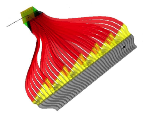
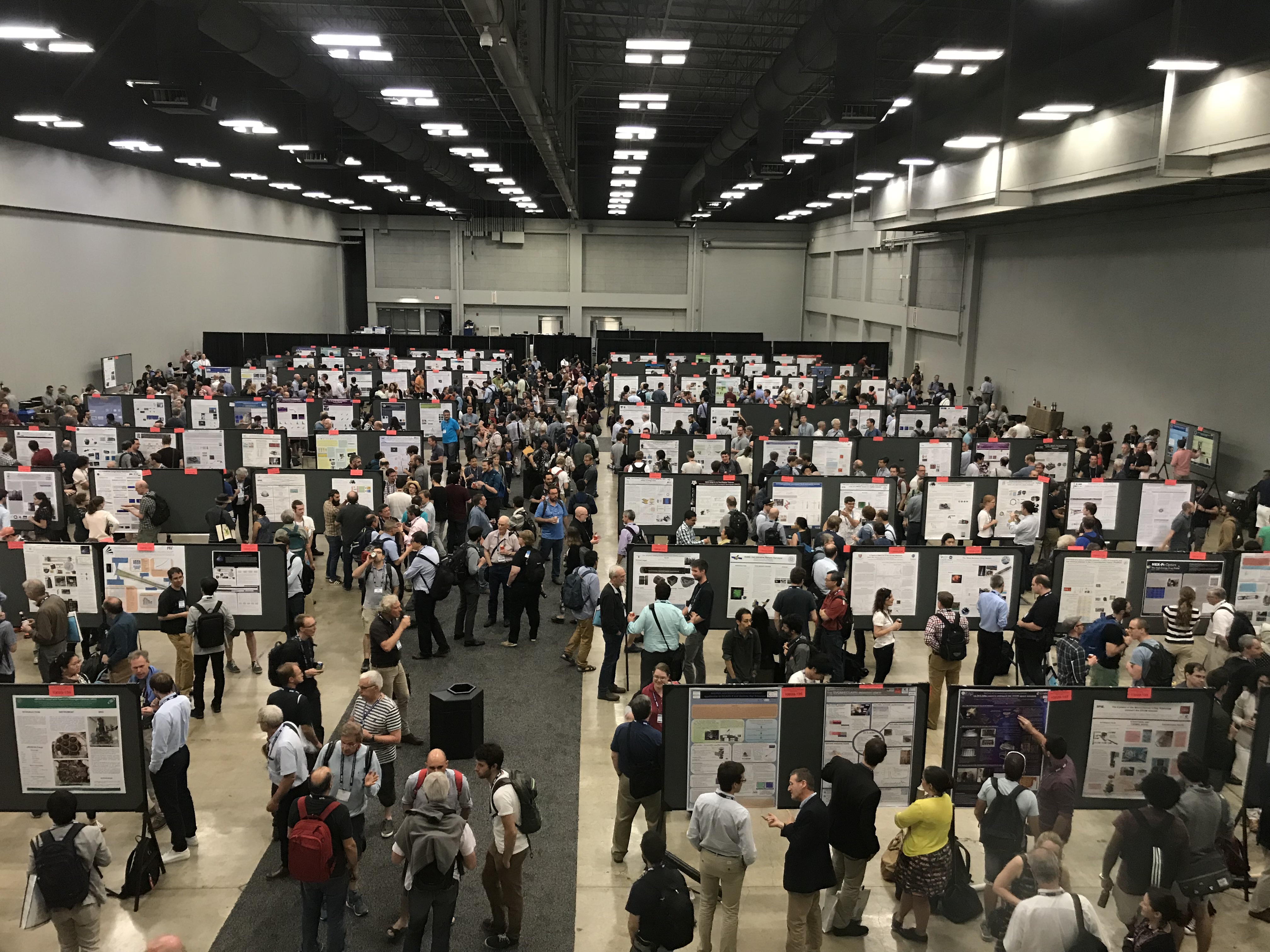
Photonic reformatters are 3D single-mode (or few-mode) waveguide structures that arbitrarily reformat the distribution of patterns of light, e.g. a 2D distribution, such a nearby galaxy or planetary nebula, can be reformatted into a linear array of waveguides to form the entrance aperture (long slit) of a spectrograph. Also, when reformatters are combined with photonic lantern structures they can efficiently couple and reformat the distribution of a multi-mode PSF, such as that from a seeing limited of near-diffraction limited telescope, into single-mode linear arrays of waveguides to enable highly efficient, stable, small and cost-effective diffraction-limited spectrographs even when the input image quality is not diffraction limited. This has huge potential benefits for science cases that require high precision and high throughput, e.g. visible/NIR spectroscopy on ground-based telescopes. The collaboration has been developing the models of devices and systems to optimise the design parameters required to match the fabrication techniques (ULI, fibre and 3D printing) whilst maximising the device/system performance. Full device and system modelling and optimisation is being carried out on a reformatter concept for the University of Leiden for a single mode integral field unit for large telescopes with extreme adaptive optics systems, also a reformatter for improving the light coupling for the Minerva-red instrument is under development. Once the concept development is complete, both devices will be fabricated and verified by the OPTICON consortium. Another activity has been the development of a novel new image slicer concept combining conventional mirror-based image slicing technology with photonics lantern and reformatter technologies. These developments were presented at the SPIE Astronomical Instrumentation 2018 conference in Austin .
WP6.4 Modelling and optimisation of AO coupling with photonic devices
Initial on-sky results with photonic devices installed on the CANARY adaptive optics (AO) system at the William Hershel Telescope (WHT) on La Palma, performed as part of the OPTICON FP7.2 Astrophotonics development, showed that use of PSF optimisation of AO routines could greatly improve the coupling efficiency into photonic device. Furthermore, the baseline operating mode of the ELT provides for an AO-corrected image. Therefore, it is essential that we are able to design and fabricate photonic devices that optimally couple to the AO corrected telescopes and well as optimally tune the AO systems for coupling into photonic devices. The main aims of this work- package are summarised below:
- Develop the optimisation of photonic designs to efficiently couple to AO corrected telescopes.
- Understand how best to optimise AO system to couple into photonic devices (including standard multi-mode optical fibres).
- Develop a laboratory testbed facility for the characterisation of photonic devices and optimisation of the AO system photonic coupling.
- On sky-testing of photonic devices with the CANARY AO system at the WHT.
- Investigate the potential of photonic devices to provide AO function, such as low order wavefront sensing.
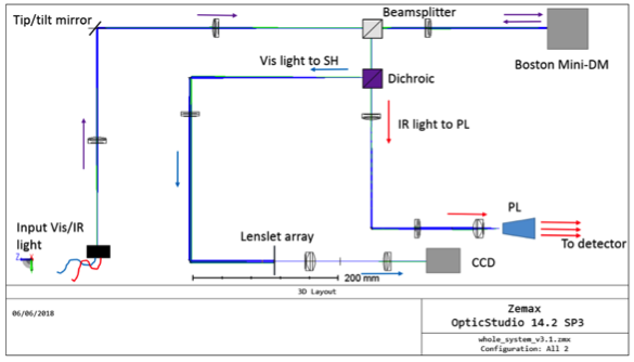
Extreme AO systems provide an almost diffraction limited images that should be, in principle, ideal for coupling into single mode fibres. However, any system vibrations can cause the diffraction limited image to move around over the input face of the fibre, drastically reducing the coupling efficiency. The ZAH is pioneering a novel tip-tilt coupling device concept to sense these vibrations at the focal plane using 3D printed microlenses. A tip-tilt mirror can then be used to correct the image motion induced by the vibrations and thereby re-optimise the coupling into the fibre. A full system demonstrator is being developed for testing at the KOOL AO testbed facility in Heidelberg and if successful it will be further tested on iLocater front end prototype at the Large Binocular Telescope (LBT) in Arizona.
A second all-fibre wavefront sensor as a lens free alternative to a Shack-Hartmann wavefront tip-tilt sensor has been developed and tested at the University of Bath. The device is based on a multi-core optical fibre that contains three identical single-mode cores symmetrically positioned at the corners of an equilateral triangle in the fibre cross-section (Figure 8). The fibre acts like the lens in a Shack-Hartmann wavefront sensing element converting phase variations at the input (due to wavefront tilt) into intensity variations at the output, from which both the magnitude and the direction of moderate wavefront tilts can be deduced. This device enables the sensing of wavefront tilt to be physically remote from detection system, in a compact all-fibre structure. A complete analytical theory relating tilt and power distribution has been derived, with a remarkably simple interpretation. Preliminary results from the testing of the device were presented at SPIE Photonics Europe 2018, however, as yet the device performance does not fully match the theoretical modelling. It is believe the problem is understood and future design can be tailored to address the discrepancy. It is envisaged that a full wavefront sensor array could be constructed from a multi-core fibre containing many such groups of three cores, tapered at one end and connected to a remotely-placed sensor array at the other. This would be able to reconstruct an extended wavefront.
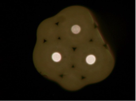
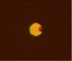
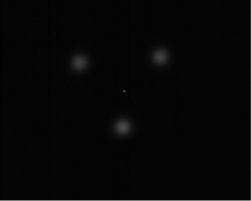
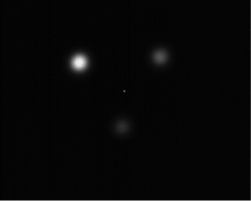
Figure 7 Left - Optical micrographs of the cross-sections of the 3-core fibre before (diameter 105 μm, core separation 40 μm, core diameter 10 μm, NA = 0.11). Mid left - Cross-section after tapering (diameter 14 μm). Mid right - Near-field images of the output end- face of the 3-core fibre when the input end-face was parallel to the incoming wavefront. Right – End-face tilted w.r.t. wavefront.
Simulation activities have also looked at photonic lantern geometries that can provide unambiguous information on both tip/tilt and higher order wavefront terms. The simulations address devices that are mode-matched for operation at near infrared wavelengths, where current generation adaptive optics systems are optimised. Initial results for a five-mode lantern with the cores arranged in a quincunx pattern have shown three main results:- Tip and tilt at the fibre tip can accurately be retrieved using light coupled into the outer 4 cores only
- Flux in the central core matches single mode fibre throughput across a narrow wavelength range only (for the studied device)
- By comparing the output of the four outer cores at multiple wavelengths wavefront tip, tilt and defocus can be retrieved.
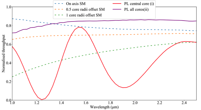
Figure 8 shows the throughput (coupling efficiency) versus wavelength of a 5 core photonic lantern compared to that of a single mode fibre, the solid lines are for the 5-core photonic lantern and the dashed lines are for the single-mode fibre. The single-mode fibre throughput has been simulated for three image offset positions at the fibre input and compared to a perfectly centred image at the photonic lantern input. The results indicate that science light between 1400 -1800 nn can be directed into the central core whilst light beyond this range is coupled into the outer cores and could be used for tip-tilt/focus sensing. Shifts in focus change the phase and periodicity of beat-length between the cores, so the focus and possibly high-order aberrations can be analysed.
WP6.5 Coordination, Outreach, innovation and dissemination
The aims are to efficiently and effectively coordinate and disseminate astrophotonic developments within astronomy and other disciplines.
To this end there have been numerous collaborative development activities both within the consortium and with external collaborators. There has been a particularly strong collaboration and engagement with/from ZAH. There have also been 12 publications and presentations at several international conference and workshops, including significant representation at the recent Astronomical Instrumentation SPIE conference in Austin, Texas. The plans for the another Astrophotonics Summer School are still ongoing as we have not yet found a suitable venue and raised sufficient funds to hold the event.